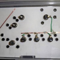
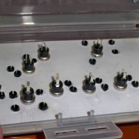
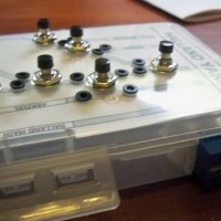
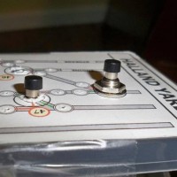
I wired the push buttons up and connected them to the SRC8. I used a couple of tape-on copper strips for common grounds. Soldering to the strip...
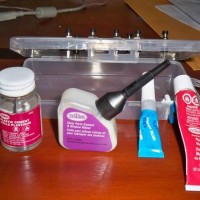
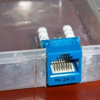
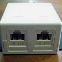
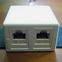
I had to I tried 4 types of glue to get the Cat5 keystone jack to stick to the enclosure. None of them worked until I tried the Testors gel type...
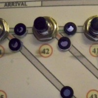
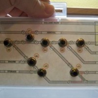
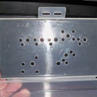
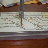
The control panel is made of a small clear plastic box 6.75in.(L) x 3.5in.(W) x 1.25in(H). The panel will be powered by Team Digital SRC8.
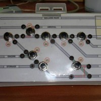
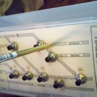
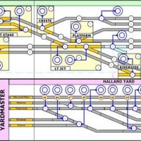
Main control panel schematic. This will be used as a background for the main control panel. Dispatcher, Yardmaster, and locals can use this panel.
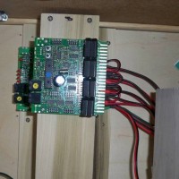
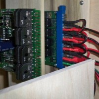
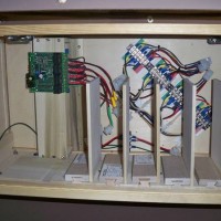
Major layout electronics modules will be housed in the staging bungalow. Including PM42, BDL168, & DS64. There is room for another BDL168...
Major layout electronics modules will be housed in the staging bungalow. Including PM42, BDL168, & DS64. BDL168 is stacked on PM42.
Major layout electronics modules will be housed in the staging bungalow. Including PM42, BDL168, & DS64. A DS64 is shown in the mounting...
Major layout electronics modules will be housed in the staging bungalow. Including PM42, BDL168, & DS64.
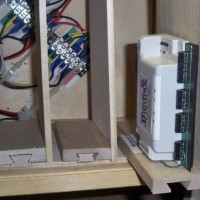
DS44 Housed in a 2 Port Keystone Jack Housing. DS44s are connected to Keystone Jacks. Frog power is also routed through the Module. Each 2 Port...